
Reading resistors color codes is easy once you understand the meaning and the math behind each band used to indicate resistance value, tolerance, and sometimes even the temperature coefficient. We’ve created a simple chart to explain resistor color coding for you.
Resistors are available in many different values, shapes, and physical sizes. Practically all leaded resistors with a power rating up to one watt have a pattern of colored bands that are used to indicate resistance value, tolerance, and sometimes even the temperature coefficient. There can be anywhere from three to six colored bands on the body of a resistor, with four bands being the most common variation. The first few bands always represent digits in the value of resistance. Then you will find a multiplier band to signify moving the decimal right or left. The last bands represent tolerance and the temperature coefficient.
Ansinor's Most Popular Resistor Kit
See related product

Let’s take a look at the resistor color code chart below and dive right in with a few examples:
How to read resistor color codes
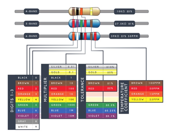
How to Read Resistor Color Codes: A Beginner's Guide to 3-Band & 4-Band Resistors
Trying to understand resistor color codes? 🎨 Learn how to easily decode 3-band and 4-band resistors — a must-know skill for every electronics hobbyist and pro!
Here’s the breakdown:
-
The first two bands give the first two significant digits of the resistance value in ohms.
-
The third band is the multiplier. It moves the decimal point to give you values ranging from milliohms all the way to megohms!
-
The fourth band (if present) shows the tolerance — how close the resistor is to its stated value.
-
No fourth band? That means it’s a 3-band resistor with a default tolerance of ±20%.
Whether you're building circuits, repairing electronics, or stocking your component kit, knowing how to read resistor bands helps you choose the right part and avoid project fails!
🔍 Looking for reliable resistors? Understanding color codes makes buying the right components faster and easier.
💬 Still have questions? Comment below 👇 or check out our full resistor guide for more tips and handy charts!
#Electronics #ResistorColorCode #DIY #ElectronicsProjects #CircuitBasics #LearnElectronics
Mastering High-Precision Resistors: Your Ultimate Guide to 5-Band & 6-Band Resistor Color Codes
Want to accurately read high-precision resistors? Understanding 5-band and 6-band resistor color codes is essential for anyone working with advanced electronics!
On 5-band resistors, the first three bands indicate the significant digits of the resistance value—giving you a more precise measurement. The fourth band acts as the multiplier, and the fifth band represents the tolerance.
For even higher accuracy, 6-band resistors add a special sixth band that indicates the temperature coefficient (measured in ppm/K). This value tells you how much the resistance changes with temperature fluctuations.
👉 For example, a brown sixth band (100 ppm/K) means the resistance value changes by 0.1% for every 10°C shift in temperature—crucial for stability in sensitive circuits!
Whether you’re designing circuits, troubleshooting, or buying resistors for your projects, knowing how to interpret these color bands can save you time and improve performance.
🔍 Looking for reliable high-precision resistors? Understanding color codes helps you choose the right components for professional and DIY electronics!
💬 Got questions about resistor codes? Drop a comment below or check our full guide on reading resistor color bands!
#Electronics #ResistorCodes #DIYElectronics #Engineering #CircuitDesign #PrecisionResistors
Common resistor color code questions:
How do I know which end of the resistor to start reading from?
- Many resistors have some of the color bands grouped closer together or grouped toward one end. Hold the resistor with these grouped bands to your left. Always read resistors from left to right.
- Resistors never start with a metallic band on the left. If you have a resistor with a gold or silver band on one end, you have a 5% or 10% tolerance resistor. Position the resistor with this band on the right side and again read your resistor from left to right.
- Basic resistor values range from 0.1 Ohm to 10 Megaohms. With that knowledge, realize that on a four-band resistor the third color will always be blue (106) or less and on a five-band resistor, the fourth color will always be green (105) or less.
What role does a resistor play in a circuit?
Think of a resistor as the component that actively limits or controls the flow of electrical current in a circuit.
In simpler terms, if electricity flowing through a wire is like water flowing through a pipe, a resistor is a narrow section of that pipe. It makes it harder for the water (electricity) to gush through freely.
Here’s what that actually lets you do:
-
Protect Components: This is its most important job. Many components, like an LED, are very delicate and will instantly burn out if too much current flows through them. A resistor acts as a guardian, limiting the current to a safe level. You'd never power an LED directly without a resistor.
-
Control Voltage (Voltage Division): Resistors can be used to create a specific voltage at a certain point in a circuit. By placing two resistors in series, you can "divide" the total voltage, providing a lower voltage to a specific component. This is a fundamental technique for sensors and many ICs.
-
Generate Heat: When current is forced through a resistor, energy is lost as heat. This is actually the desired effect in appliances like toasters, space heaters, and incandescent light bulbs (where the filament is a type of resistor).
In short, a resistor doesn't create power; it manages it. It's the fundamental component used to impose control and order on the flow of electricity, making sure every other part of the circuit gets the right amount of current and voltage to work properly.
What is a zero-ohm resistor?
Easily recognized by their single black band, zero-ohm resistors are basically wire links used to connect traces on a printed circuit board. They are packaged like a resistor so the same automated equipment used to place resistors can also be used to place these on the circuit board. This design prevents the need for a separate machine to install a jumper wire.
Is there a fancy way to memorize the order of colors on the chart?
While there are several mnemonics on the internet to help you memorize the color order for the resistor color code chart, some are more pleasant than others. Another way to set the color chart to memory is to think of black as the absence of color, so it is “0”, while white is the combination of all colors, so it is the highest value, “9”. In the middle of the color chart you will find the standard rainbow colors in order for numbers 2 through 7, so your childhood ROY-G-BIV acronym comes into play, minus the color indigo. Just remember that brown fits between black and red as number “1” and grey fits between violet and white as “8” and you’ve got it!
What is a “reliability” band?
Military specified resistors often include an extra band on four-band resistors to indicate reliability, or the failure rate (%) per 1000 hours of service. This is seldom utilized in commercial electronics.
History of the resistor
Before the familiar ceramic tube, the earliest resistors were literally just pieces of clay or charcoal with wires attached! In the 19th century, scientists needed to control current in their experiments, so they used whatever conductive materials they could find. They'd use different lengths or compositions of iron, copper, or carbon to get roughly the right resistance. It was messy, unstable, and highly imprecise.
In 1872, Englishman Charles Garnier patented the first real "carbon composition resistor." The key ingredient? Carbon! Imagine finely ground carbon powder (like pencil lead) mixed with a ceramic binding material (like clay) and baked. This created a reliable resistive element. This technology was a workhorse for nearly a century because it was cheap to make and handled power surges well.
In the 1920s, as radios exploded in popularity, technicians were constantly soldering the wrong resistors into circuits. To solve this, the Radio Manufacturers Association (RMA) introduced the color band code around 1930. This was a genius move! It was a universal language that worked even if the resistor was dusty, soldered in place, or from a different manufacturer. It made assembly and repair faster and more reliable, fueling the electronics boom.
The carbon resistor's downside was its poor tolerance and stability. The space race and military needs in the mid-20th century demanded something better. This led to the development of film resistors – carbon film and, later, ultra-precise metal film resistors. Instead of a chunky carbon mix, these used a thin, vapor-deposited film of resistive material on a ceramic rod. This allowed for incredibly tight tolerances (like ±1% or better), stability, and lower noise, making modern computers and spacecraft possible.
The 1980s brought the next giant leap: Surface-Mount Technology (SMT). Resistors (and other components) shrank from wire-ended cylinders into tiny, flat, rectangular chips without leads. These SMD (Surface-Mount Device) resistors are placed by robots onto circuit boards at blinding speeds. This allowed for the miniaturization of everything from smartphones and laptops to medical devices. The classic "banded" resistor is still used, but it's now mostly for hobbyists and specific cases – the vast majority of the billions of resistors made today are these tiny, invisible chips.
Now that you know the basics and tricks for reading resistor color codes, get out there and impress all your friends!